
Introduction: A Queue at Dusk, Numbers on the Screen, and One Big Why
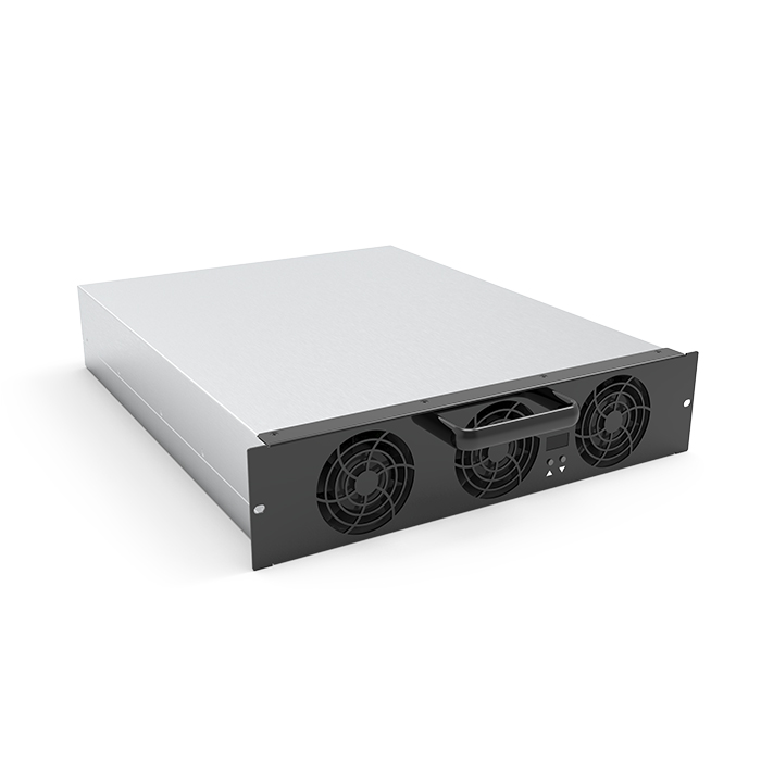
A driver pulls in at dusk. Three cars wait, one charger blinks “reduced power,” and the station host shrugs. Power drops, lines grow, and tempers rise. The power module for EV charger is often the hidden reason. In many sites, logs show up to 25–30% performance dips at peak hours, usually tied to heat, grid sag, or aging components—small things that stack up. So we ask: why do some chargers keep pace, while others throttle and stall?
In Thailand and across ASEAN, we want fast charge that feels simple, stable, and fair (chai mai?). The scene above happens more than we like. Data points say efficiency claims on paper do not match street reality when air temps hit 35°C and traffic spikes after work. Is it the topology, the control loop, or the cooling path? The answer is not one thing. It is how the system breathes. And how the module handles stress. Let’s compare how different module choices shape the outcome—then move forward to better options.
Hidden Pain Points Behind Similar-Sounding Specs
Why do chargers fail quietly?
On datasheets, many DC blocks look equal. But system behavior tells another story. Ripple management in the DC link, soft-switching range, and the quality of isolation under surge shape the real uptime. A module may promise 96% peak efficiency, yet spend hours outside its sweet spot. Once ambient rises, the control loop widens, conduction loss grows, and thermal derating starts. Look, it’s simpler than you think: poor coupling between the PFC stage and the DC-DC converter pushes more heat into the magnetics, not just the heatsink—funny how that works, right?
Real pain points hide in the edges. CAN bus timing that drifts under noise can cause minute-scale hiccups. An LLC resonant stage that is not tuned for wide battery voltages spends too long at partial soft switching. SiC MOSFETs help, but only if gate drive and snubbers are matched to the layout. The EMC filter can also force extra loss if the busbar geometry is not tight. Users feel this as slower charge above 60% SOC, or random cutbacks during lunch rush. What reads as “grid issue” is often module behavior under harmonics and heat. When modules are designed with tight thermal paths, adaptive dead-time, and good isolation barrier design, those small drifts go away. Station hosts see fewer restarts. Drivers see steadier kilowatts. Same headline wattage, different lived result.
New Principles That Change the Curve
What’s Next
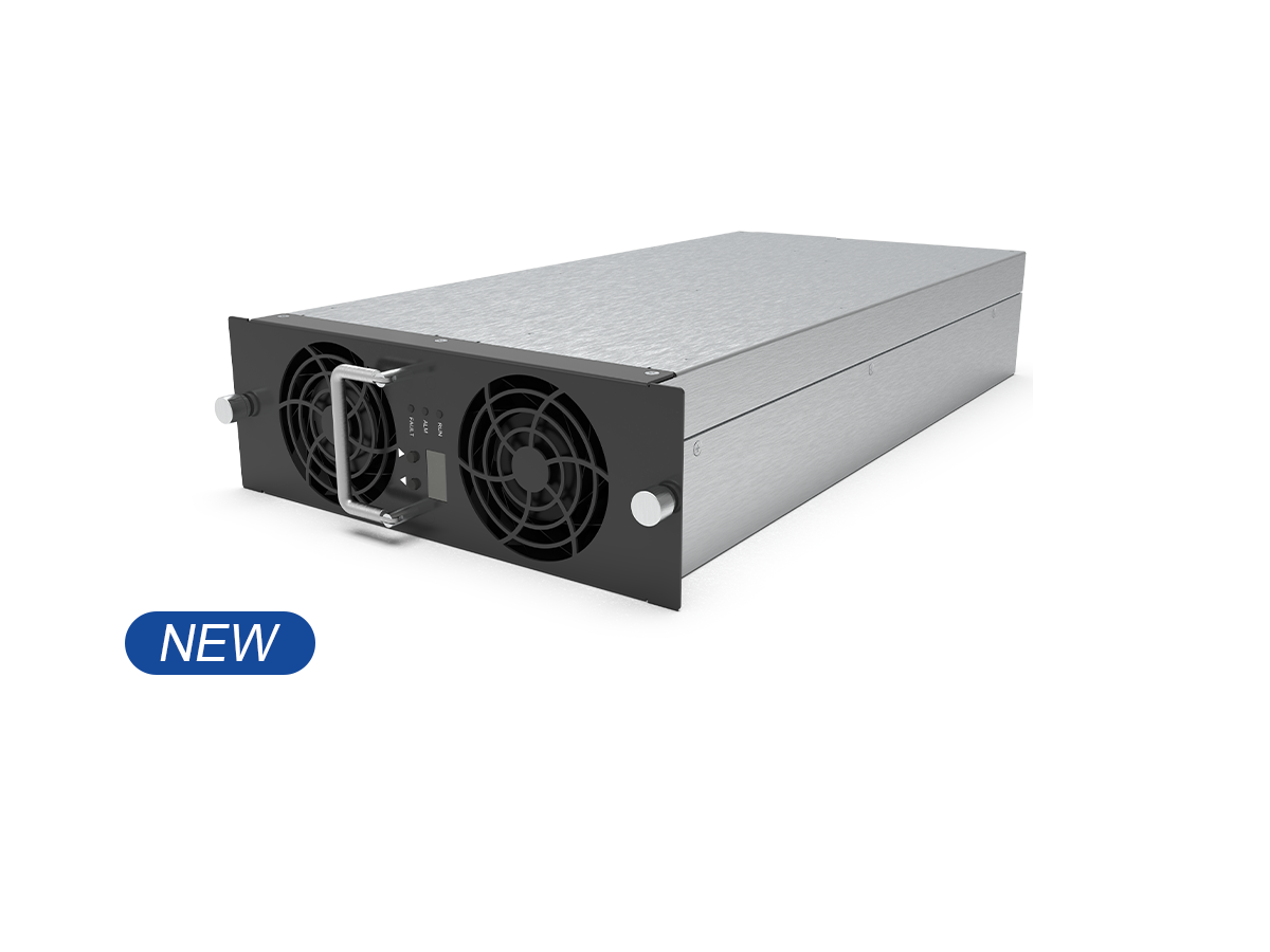
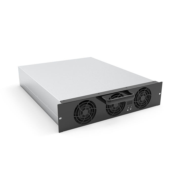
The shift is not only about higher ratings. It is about keeping soft switching and clean current over a broader range, even as cables warm and packs vary. Wide‑bandgap devices, like SiC MOSFETs, enable higher switching speeds without harsh losses. But the key is the system around them: digital control that adjusts resonant frequency in real time, better current sensing near the busbar, and smarter thermal maps. Modules that anchor these ideas—such as designs in the class of —use isolation that resists common-mode spikes, and gate drives that stay stable at heat. The result: lower RMS stress on magnetics and smaller derating windows. Shorter cables, cleaner loops, quieter EMC. Small pieces, big calm.
Comparatively, legacy blocks lean on fixed dead-time and narrow LLC tuning. They hit peak numbers in the lab, then drift in the field. Newer modules keep the efficiency plateau flatter by blending adaptive modulation with a disciplined layout. You can see it on logs: fewer dips at 38°C ambient, better hold over at low grid voltage, and less chatter on the CAN bus—funny how that works, right? Summing up, uptime improves, fans spin less, and charge curves stay predictable. For teams choosing a path, focus on three checks. First, thermal headroom under worst-case inlet temps, not just 25°C claims. Second, stability across the full battery voltage window with measured THD at load steps. Third, control integrity: noise immunity on signals and repeatable protection trips. If those three are strong, you get fewer surprises and more steady sessions. That is what drivers notice, and what operators need. For more on ecosystem fit, see winline charger winline charger.